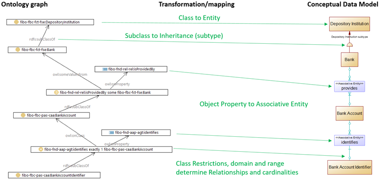
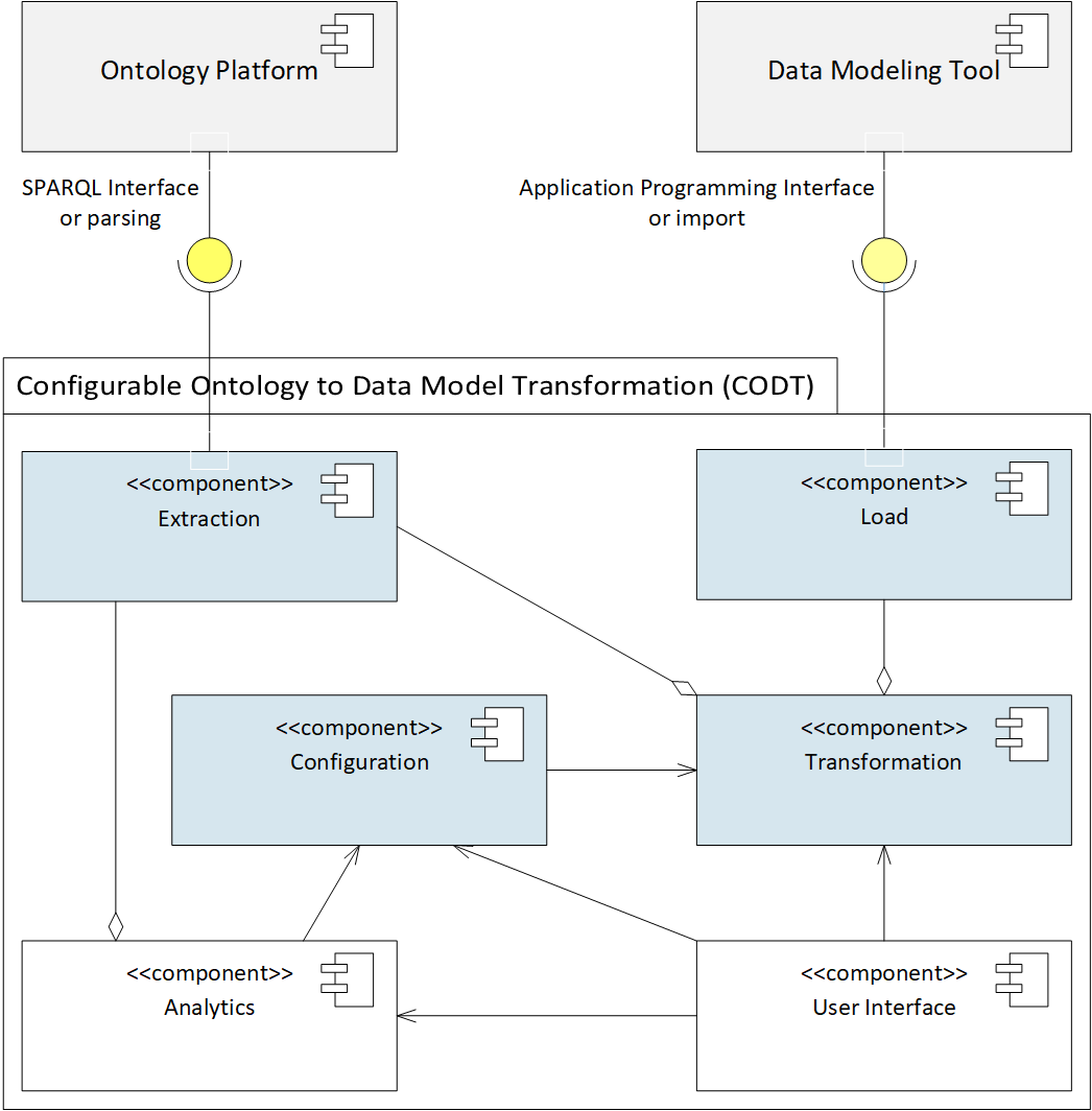
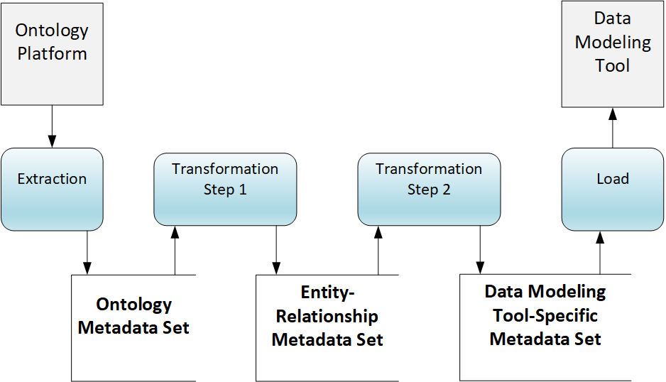
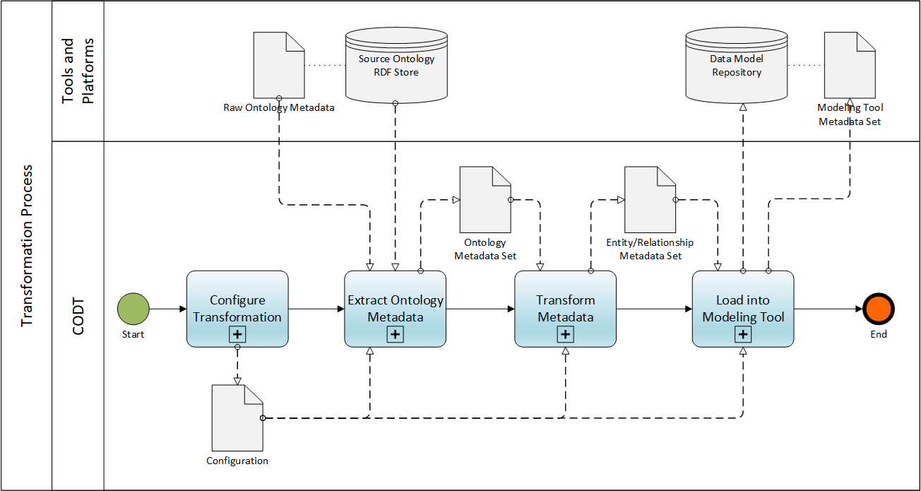
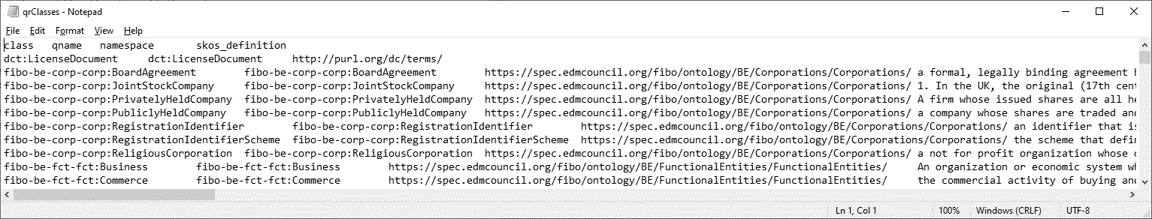
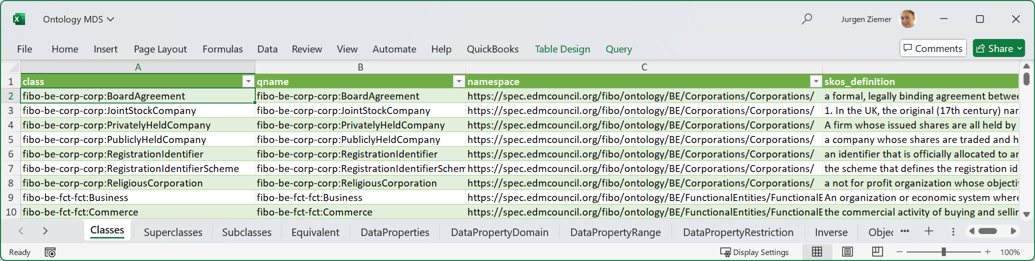
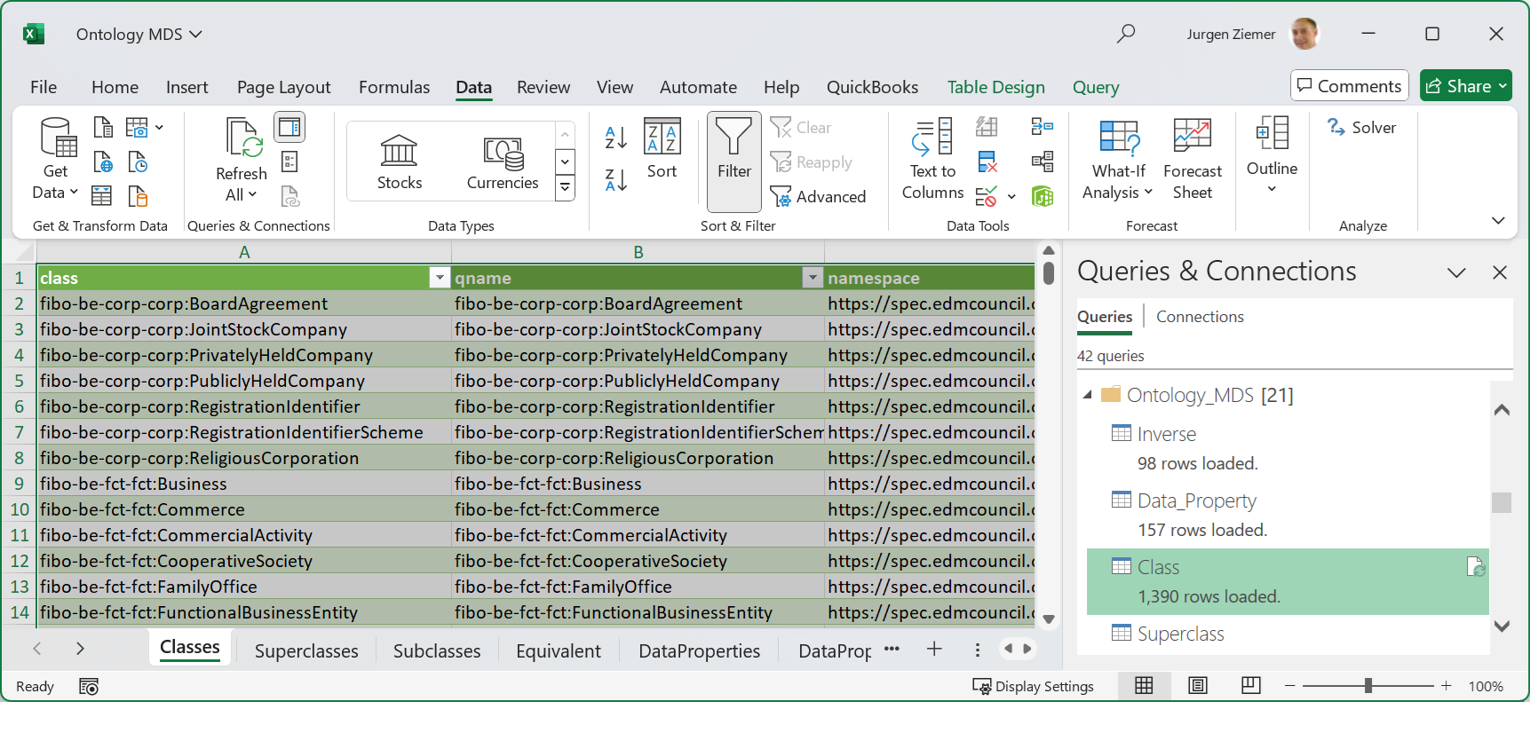
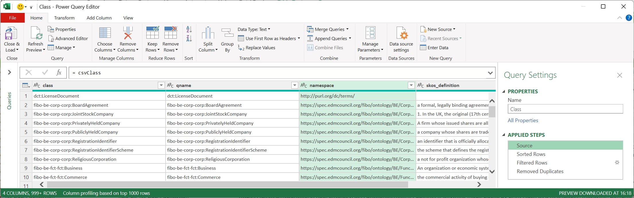
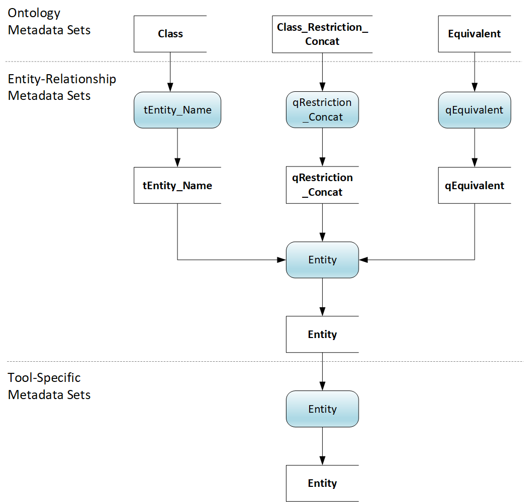
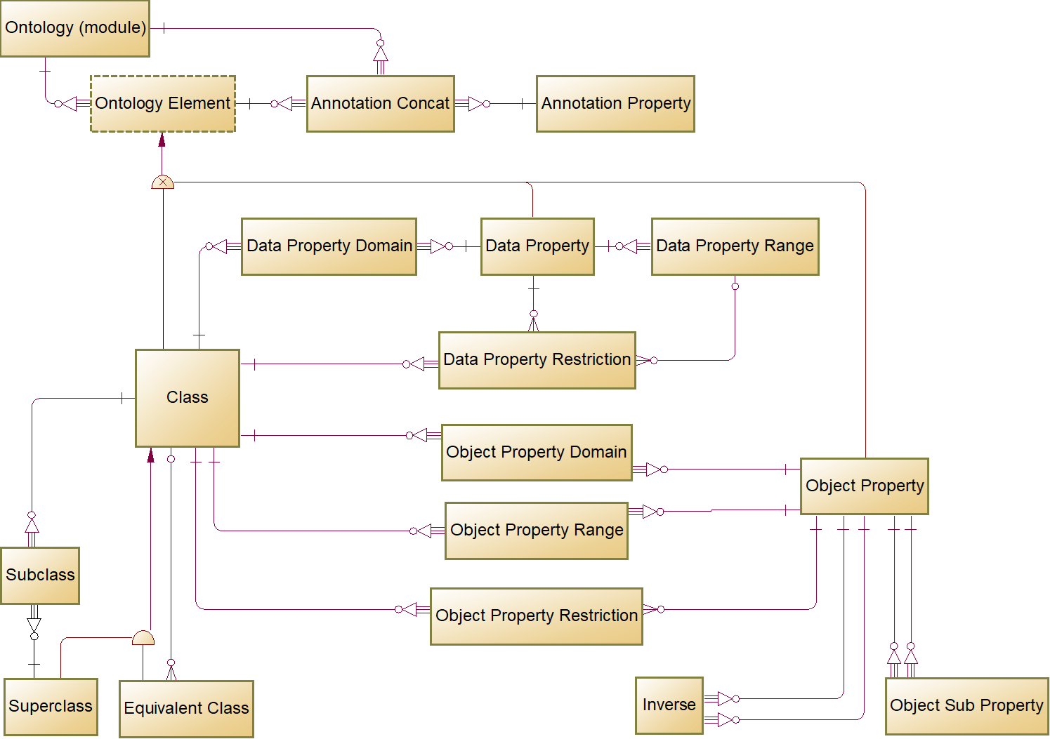
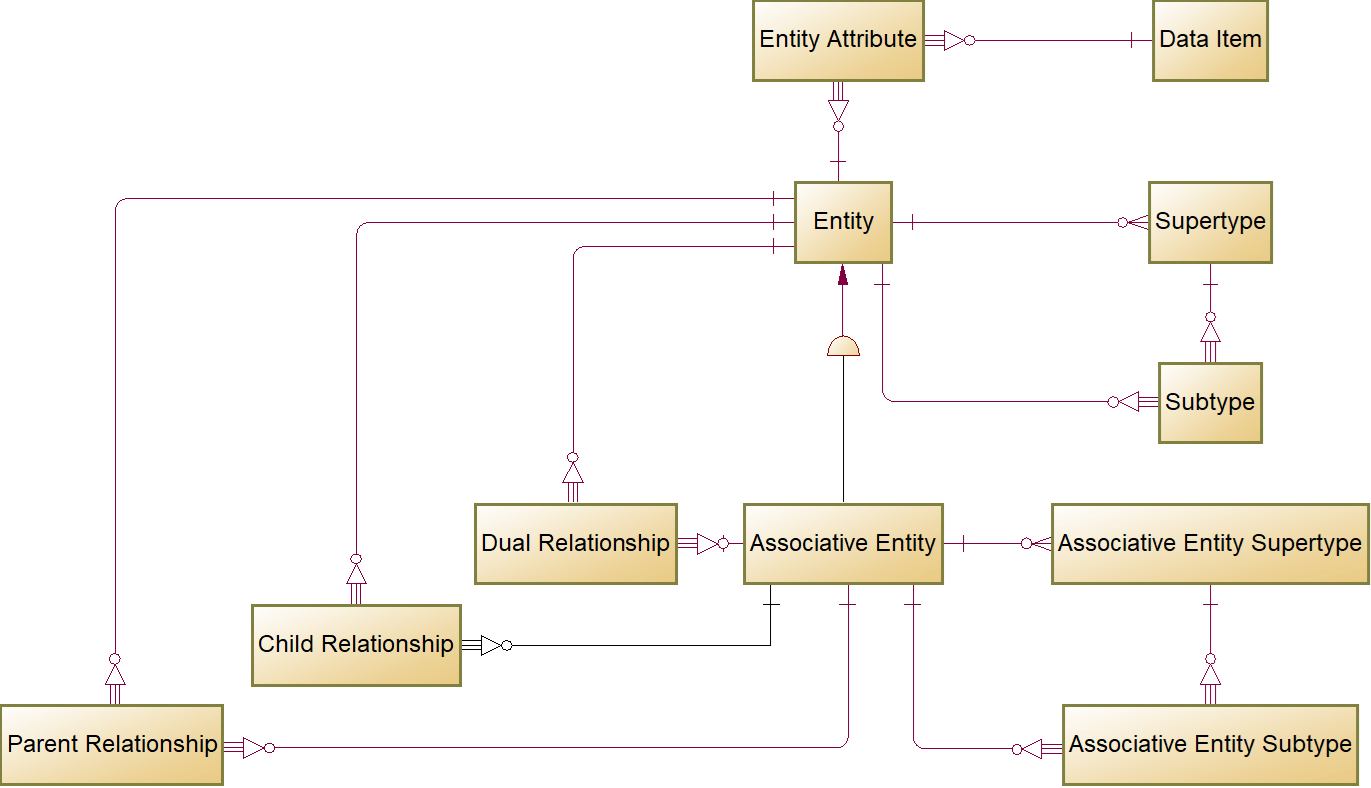
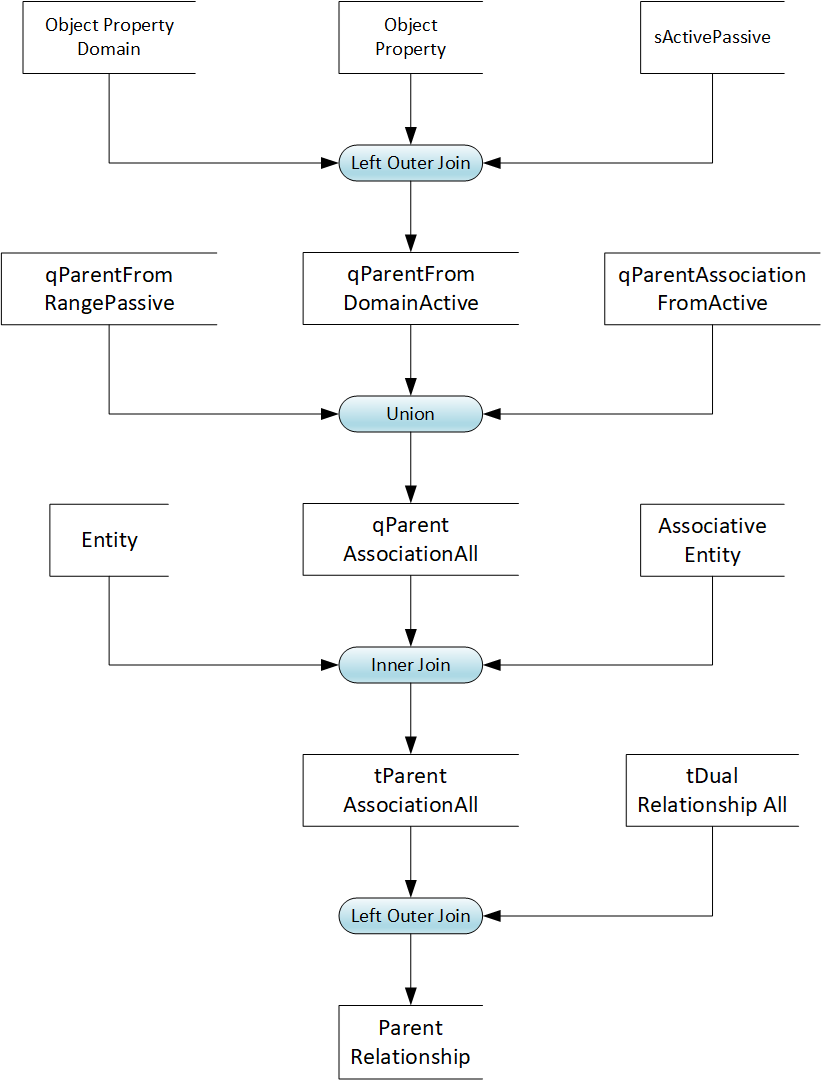
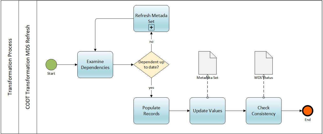
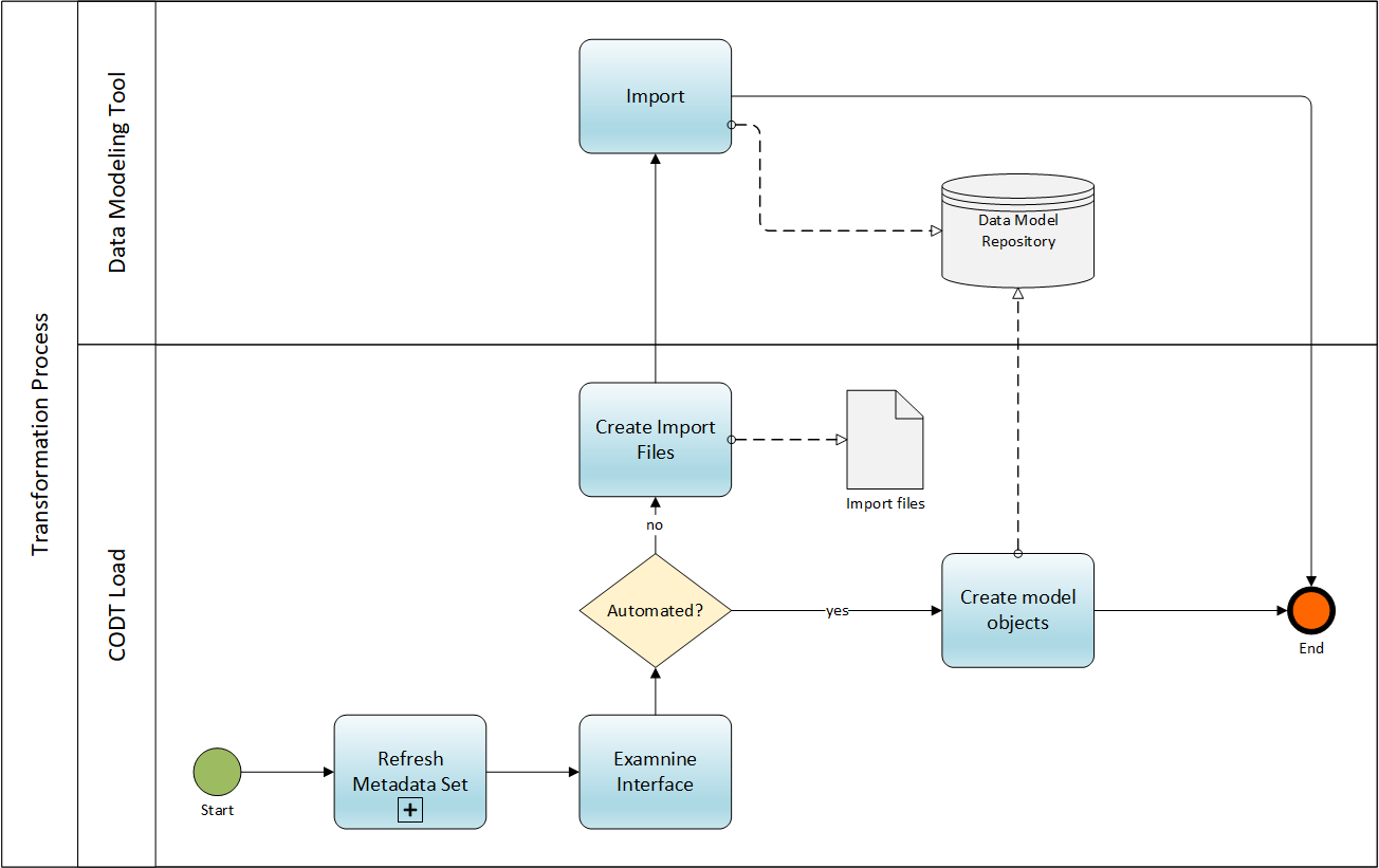
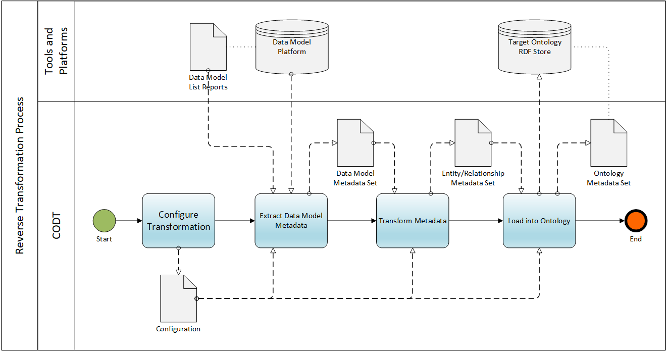
The gallery shows the Configurable Ontology to Data Model Transformation (CODT) patent drawings. Figures 1-23 are identical to the official United States Patent and Trademark publication, US12038939B2, but in color and without distracting numerals. You can click on an image to open the drawing full-size in a new tab.